Categories
Quick Search
Monthly Special Products
News
Contact Us
Company Name:wanxinghong
Address:Dongguan Dongcheng Dongguan Long Road West, No. 2


Free customer service hotline:
 (China)
 (Taiwan)
Technical ApplicationsAre you here: Home > News > Technical Applications
What Is A Control System?
Createtime:2017-03-09
What Is A Control System?
In most systems there will be an input and an output. This block diagram represents that. (Control system designers and engineers use block diagrams to represent systems. Get used to them.) Signals flow from the input, through the system and produce an output.
· The input will usually be an ideal form of the output. In other words the input is really what we want the output to be. It's the desired output.
· The output of the system has to be measured. In the figure below, we show the system we are trying to control - the "plant" - and a sensor that measures what the controlled system is doing.
· The input to the plant is usually called the control effort, and the output of the sensor is usually called the measured output, as shown below in the figure.
For example, if we want the output to be 100oC, then that's the input.
If we want to control the output, we first need to measure the output. Within the whole system is the system we want to control - the plant - along with a sensorthat measures what the output actually is.
· In our block diagram representation, we show the output signal being fed to the sensor which produces another signal that is dependent upon the output.
· A sensor might be an LM35, which produces a voltage proportional to temperature - if the output signal is a temperature.
We need the sensor in the system to measure what the system is doing.
· The sensor measures the output of the system we are controlling.
· It often converts the output into a variable we can use. If the output is a temperature, we might want to have a voltage we can use to control a heater, for example. The LM35 temperature sensor, for example, produce .01 volts for every 1.0oC change.
To control the system we need to use the information provided by the sensor.
· Usually, the output, as measured by the sensor is subtracted from the input (which is the desired output) as shown below. That forms an error signal that the controller can use to control the plant.
· The device which performs the subtraction to compute the error, E, is a comparator.
Finally, the last part of this system is the controller.
· The controller acts on the error signal and uses that information to produce the signal that actually affects the system we are trying to control.
· The controller has to provide enough power to drive the system. You don't want to try to control a large motor with a 741 operational amplifier. You just can't do that, so the controller has to be able to compute the control signal, and it has to be able to drive the system you are trying to control.
· Thus, the controller has two things that it has to achieve.
o The controller has to compute what the control errort should be.
o The controller has to apply the computed control effort.
Consider how this controller works.
· If the gain in the forward path, from the error to the output, is large, then a small error can produce a much larger ouput.
o There is a certain logic to that strategy. You want a small error, but you need a control effort large enough to control the system. That seems to imply that the gain of the controller should be large.
· It looks like a good strategy would be for the controller to be a high gain power amplifier (for many control situations) because then a small error could produce the output we want, or something very close to what we want - because the error would be small.
Now, let's start to refine our model.
· Let's assume that the system we are trying to control is a linear system.
· To account for the linear dynamics, we'll show the transfer function of the system. That transfer function will be G(s).
Once we realize that we can describe the system we are controlling, the plant, we realize that we can describe all of the components in the sytem with a transfer function description.
· The sensor most likely has an output - typically a voltage - that is proportional to the physical variable it measures. That means that the transfer function is just a constant - a gain. We'll denote that by Ks.
The last item in our system is the controller. Controllers come in many varieties. The simplest - but certainly not the only one used - is a proportional controller. That's what we will consider here, but remember there are also integral controllers, and controllers that blend integral, proportional and derivative control and lots of others.
· In a proportional controller, the control action is proportional to the error, and we can represent the controller as a gain, Kp.
That completes a verbal and algebraic description of the system, but there is also a diagrammatic representation for the system. The block diagram shown below captures all of the information about the system as we have developed it above. Note, in this system, we are assuming that all of the signals are Laplace transform versions of the time signals we have been discussing, and the descriptions of the blocks in the block diagram are really transfer functions.

With this block diagram, let's review what we hope happens in this system.
1. There is an input, u(t), to the system, which we assume starts from rest. In the block diagram, that is represented by U(s).
2. The output of the system, Y(s), is measured with a sensor that has a transfer function Ks. That transfer function could have a time constant, etc., but for now we will examine it as though it is a constant.
3. There is an error, E(s), developed, particularly because the controlled system, G(s), cannot respond immediately and the feedback signal that is subtracted from the input to form the error is zero.
4. The error that is developed acts through the proportional controller, Kp, to start to move the output of the system to where we want it to be.
5. As the system continues to operate, the output of the system (described by G(s)) rises, reducing the error so that the control effort from the proportional controller gets smaller.
6. Even though the error gets smaller, if the gain of the proportional controller is large it will still provide enough output to drive the system close to where we want it to be.
This kind of system is referred to as a closed loop system, since there is a feedback signal that "closes the loop" in the system. That's a little jargon you need to learn and remember.
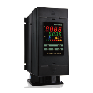
S-S Thyristor SCR power controller
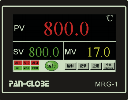
MGR1 three-in-one machine

MG900R Series Microcomputer Temperature Controller

M2000 Series
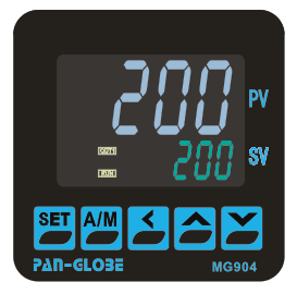
MG900 Series Microcomputer Temperature Controller

S-type Thyristor SCR power controller
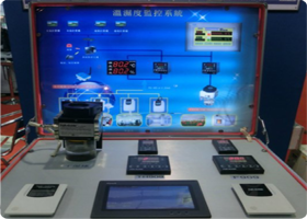
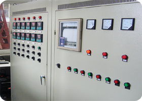
Monitor and control system applications
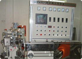
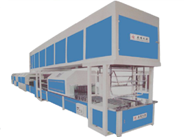
Wire and cable equipment applications
Medical equipment,simple control applications
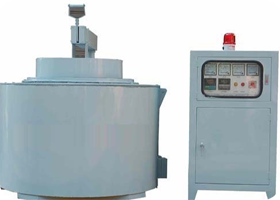
Heat treatment,food processing,annealing equipment applications
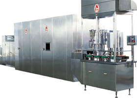
Kiln,gas,heating,textile,printing,drying,water treatment applications
Shoes machine related applications
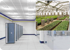
Clean room, planting field, building temperature applications
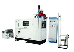
Rubber and plastic equipment applications
M900 Series High-Performancce PID Controller
P900X Series Microcomputer Temperature Controller
K900 Series Microcomputer Temperature Controller
R-2000 Series Din Rail Controller/Converter
R-2000 Series Din Rail Controller/Converter
TH900 Series Temperature And Humidity Controller
E5CWT Temperature Controller
CR Series Counter
TR Series Timer
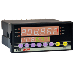
FR Series Multifunctional Frequency/Tachometer/Line Speed Meter
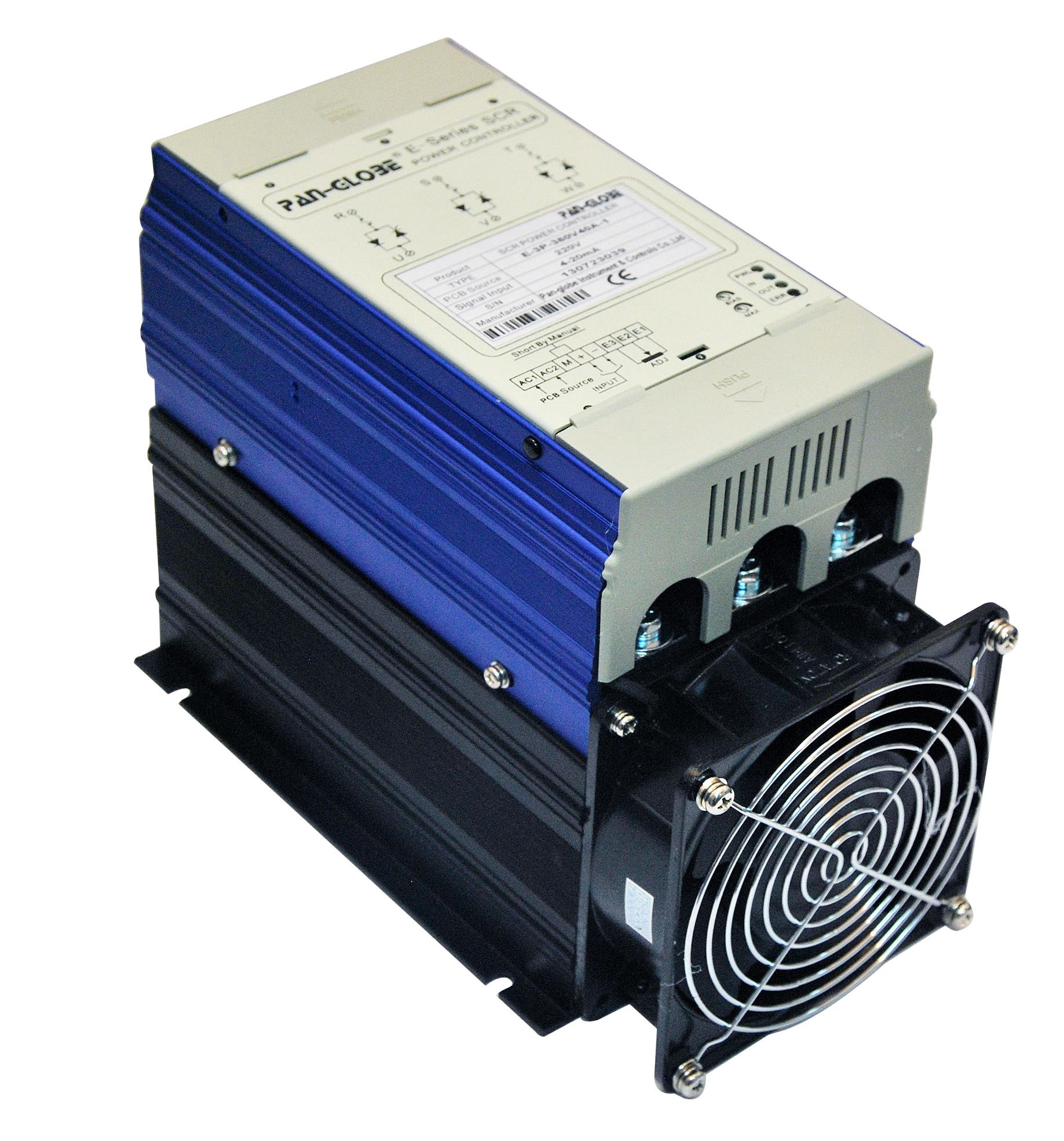
E Series SCR Power Regulator
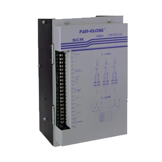
P Series SCR Power Regulator
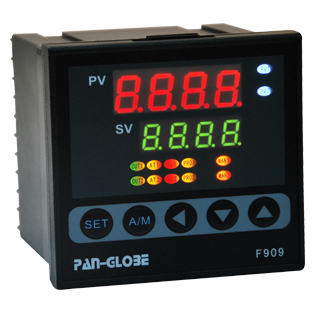
F900 Series Dual-loops PID Controller

CET Freezing And Refrigerating Machines Controller
EG Series Pressure/Level Controller
T Series Microcomputer Thumb-wheel Temperature Controller
T900 Series Microcomputer Temperature Controller
FA Series Position Meter
HR Series Timer
CB Series Counter
E4T Series Multifunctional Converter
SD Series Solid State Relay
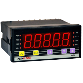
DS6 Series 4 1/2 Digital Panel Meter
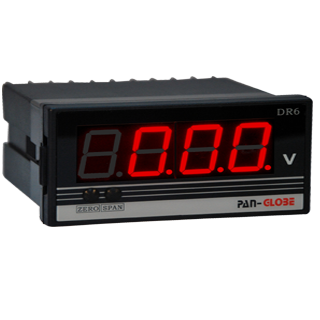
DR6 Series 3 1/2 Digital Panel Meters
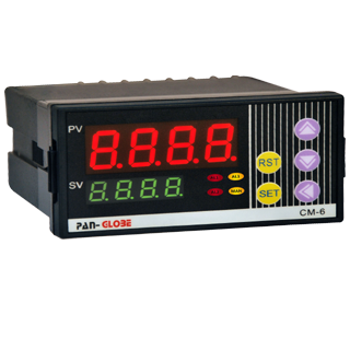
CM Series Current Monitor
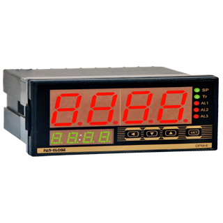
DPM-6 Series Digital Multifunction Panel Meter
Temperature And Humidity Transducer
Pressure Transmitter
CT-S Infrared Temperature Sensor

TK701-Igniter
Temterature Sensor
Proximity Sensor
Photoelectric Sensor
Links